STEP 15 - PITCHING MACHINE WHEEL
- Once the two sides of the pitching machine housing are separated, you will have access to the broken pitching machine wheel.

STEP 16 - PITCHING MACHINE WHEEL REMOVAL
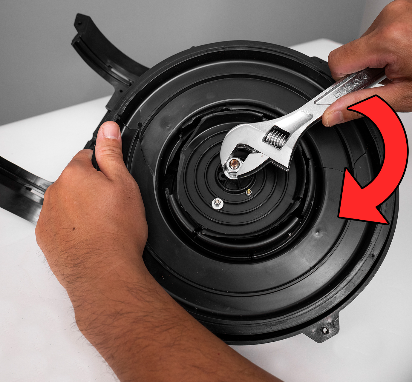
- To loosen the center nut that secures the pitching machine wheel, hold on to wheel where possible to keep it from spinning and turn the nut clockwise. Set the nut, split washer and washer aside for reassembly in a later step.
- NOTE: Before loosening the nut, you may need to remove any loose pieces of the broken pitching machine wheel.
- ⓘ Gloves may be helpful to secure a good grip on the pitching machine wheel.

STEP 17 - PITCHING MACHINE WHEEL REMOVAL
- Once the nut, split washer and washer are removed, use a flat head screwdriver to pry up the pitching machine wheel.
- NOTE: Slowly work your way around the pitching machine wheel by prying up the broken wheel a little at a time until the wheel is loose.


STEP 18 - MOTOR SHAFT
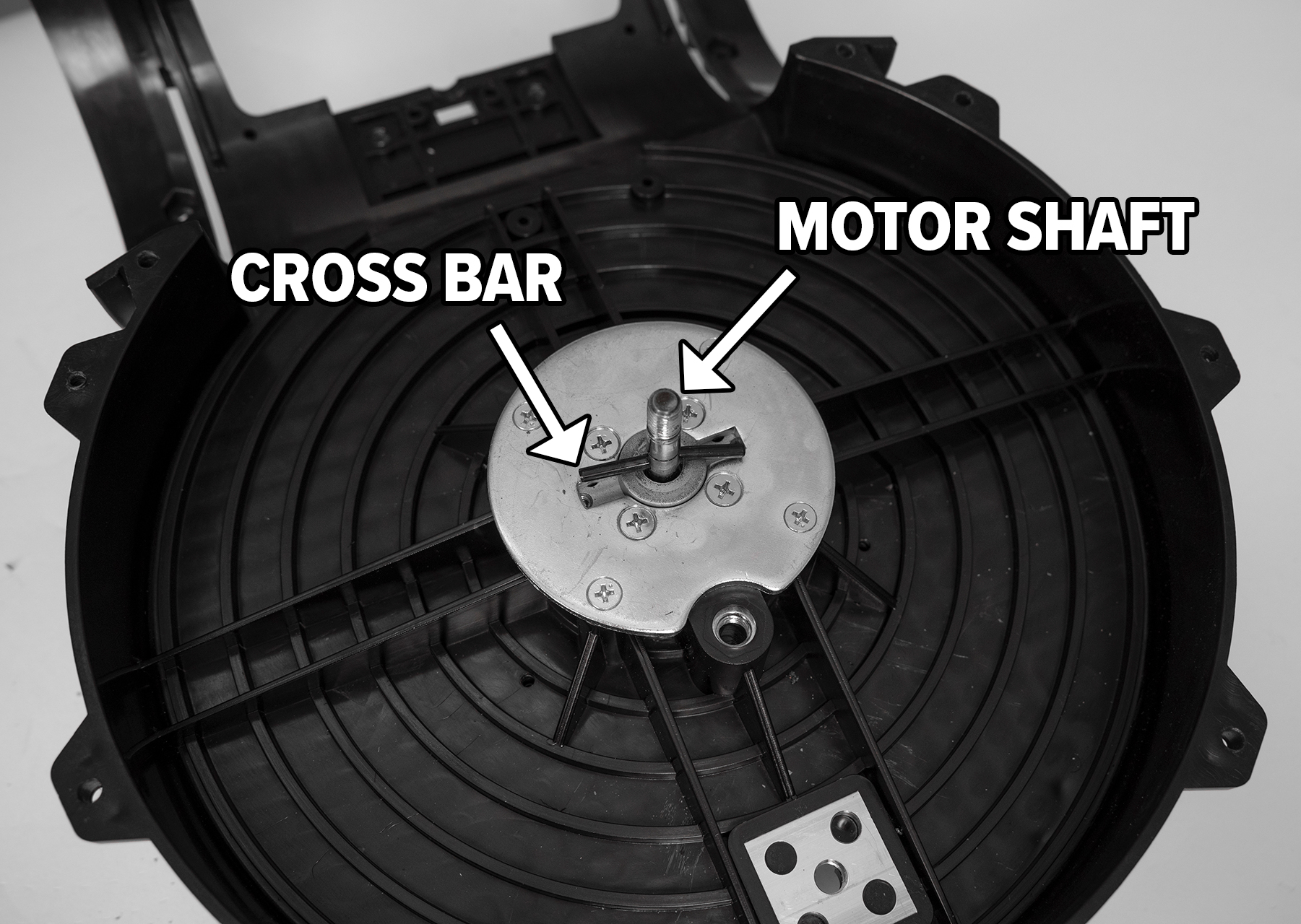
- Once the broken pitching machine wheel is removed you will see the motor shaft.
- NOTE: There is a small cross bar that goes through the main shaft. The small cross bar is responsible for engaging the pitching machine wheel.
STEP 19 - PITCHING MACHINE WHEEL INSTALL
- Prior to installing the new pitching machine wheel, rotate the motor shaft so that the small cross bar is in a 9 and 3 o’clock position. Reference image.

STEP 20 - PITCHING MACHINE WHEEL INSTALL
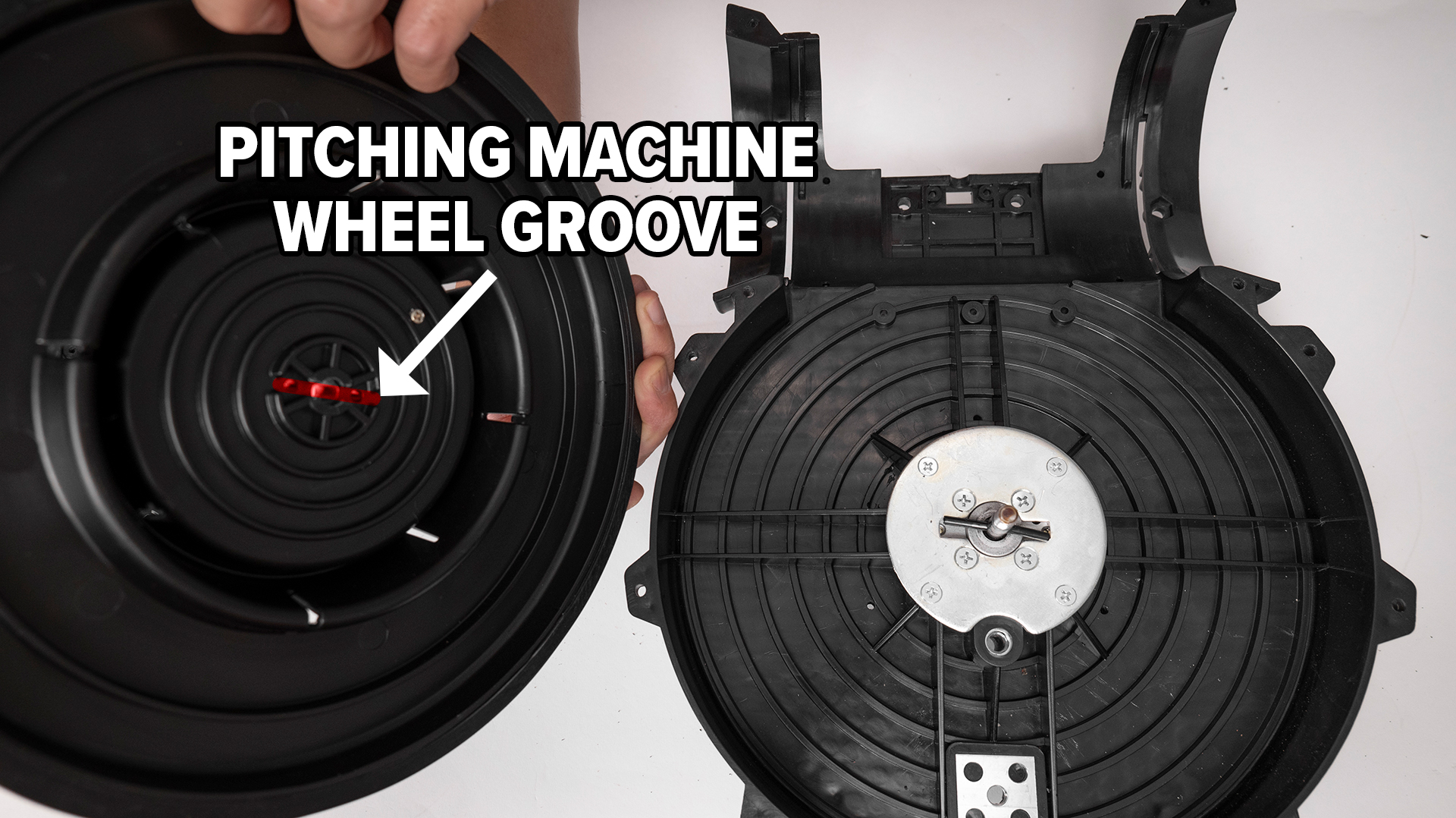
- On the back side of the pitching machine wheel there is a groove where the small cross bar of the motor shaft will nest in.
STEP 21 - PITCHING MACHINE WHEEL INSTALL
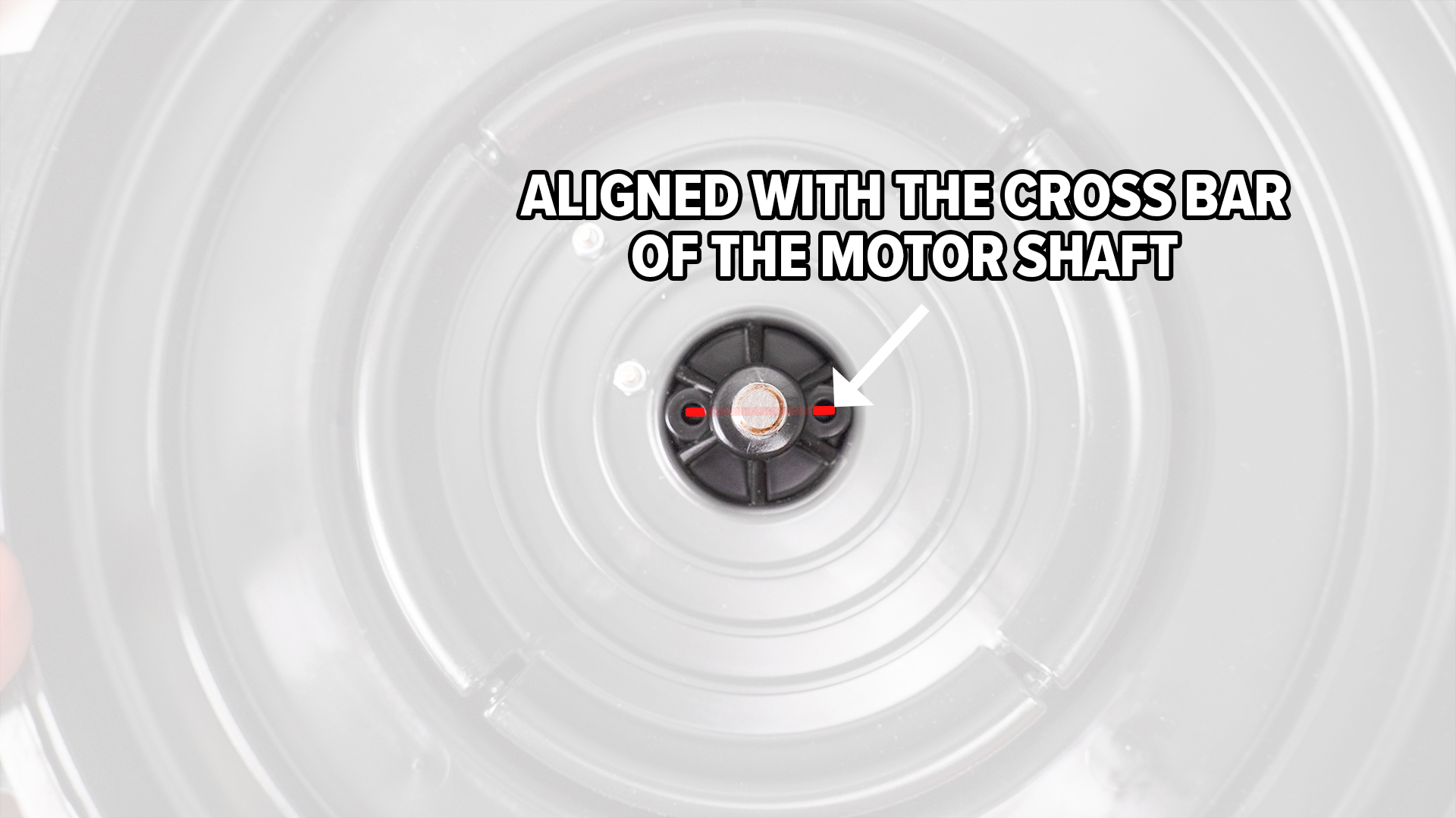
- Prior to sliding the new pitching machine wheel on the motor shaft, use the two small holes next to the motor shaft hole to make sure you are lining up the small cross bar of the motor shaft with the groove on the pitching machine wheel. Position them in the same 9 and 3 o’clock position.
- Slide the new pitching machine wheel onto the motor shaft ensuring the cross bar is seated into the groove.

STEP 22 - PITCHING MACHINE WHEEL INSTALL
- Reinstall the washer followed by the split washer.

STEP 23 - PITCHING MACHINE WHEEL INSTALL
- Reinstall the 13mm nut. With your adjustable wrench, turn counter-clockwise to tighten nut while holding the pitching machine wheel.
- NOTE: Do not over tighten the nut or the wheel will not spin freely. A good point of reference is to snug the nut down to where the wheel slightly drags when spun, then back the nut off 1/2 a turn.
- Spin the wheel to make sure it spins without resistance.

STEP 24 - PITCHING MACHINE HOUSING
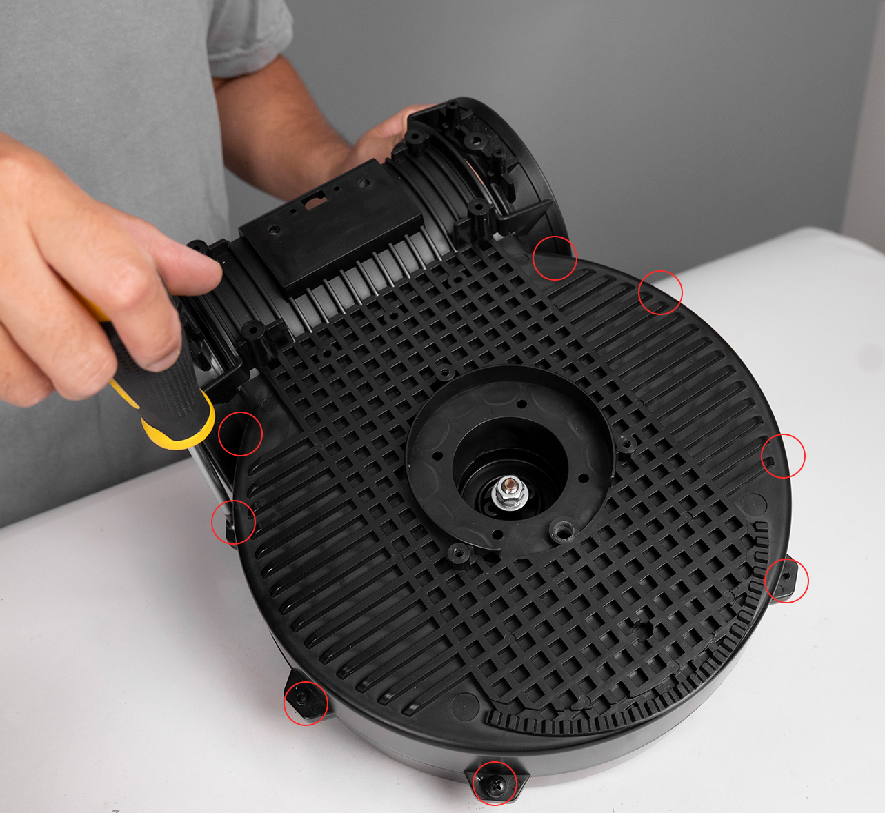
- With your Phillips screwdriver, reinstall the 8 screws to secure the two sides of the pitching machine housing.
- NOTE: The side with the flange is the side where the head of the screw sits. See reference image.

STEP 25 - PITCHING MACHINE HOUSING
- With your Phillips screwdriver and pliers, reinstall the front housing spacer.

STEP 26 - TILT BRACKET
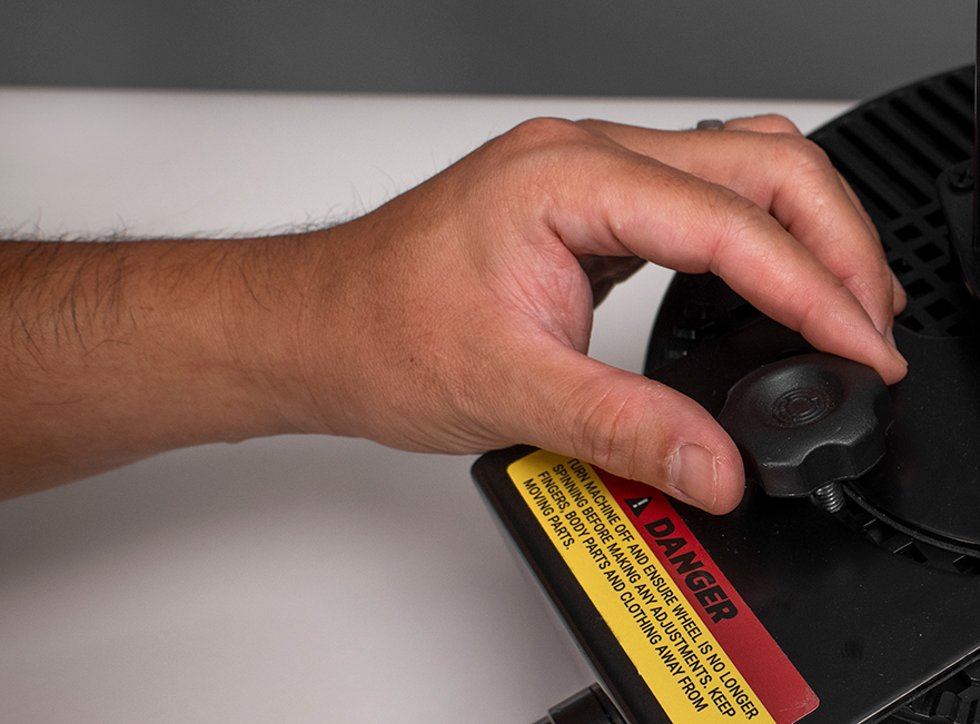
- Slide the tilt bracket back onto the pitching machine body.
- To help line things up, first reinstall the tilt adjustment thumb screw by screwing in by hand.

STEP 27 - TILT BRACKET
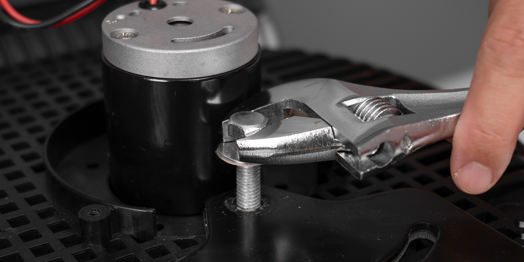
- With your adjustable wrench, reinstall the 12mm bolt and washer for the tilt bracket.

STEP 28 - TILT BRACKET
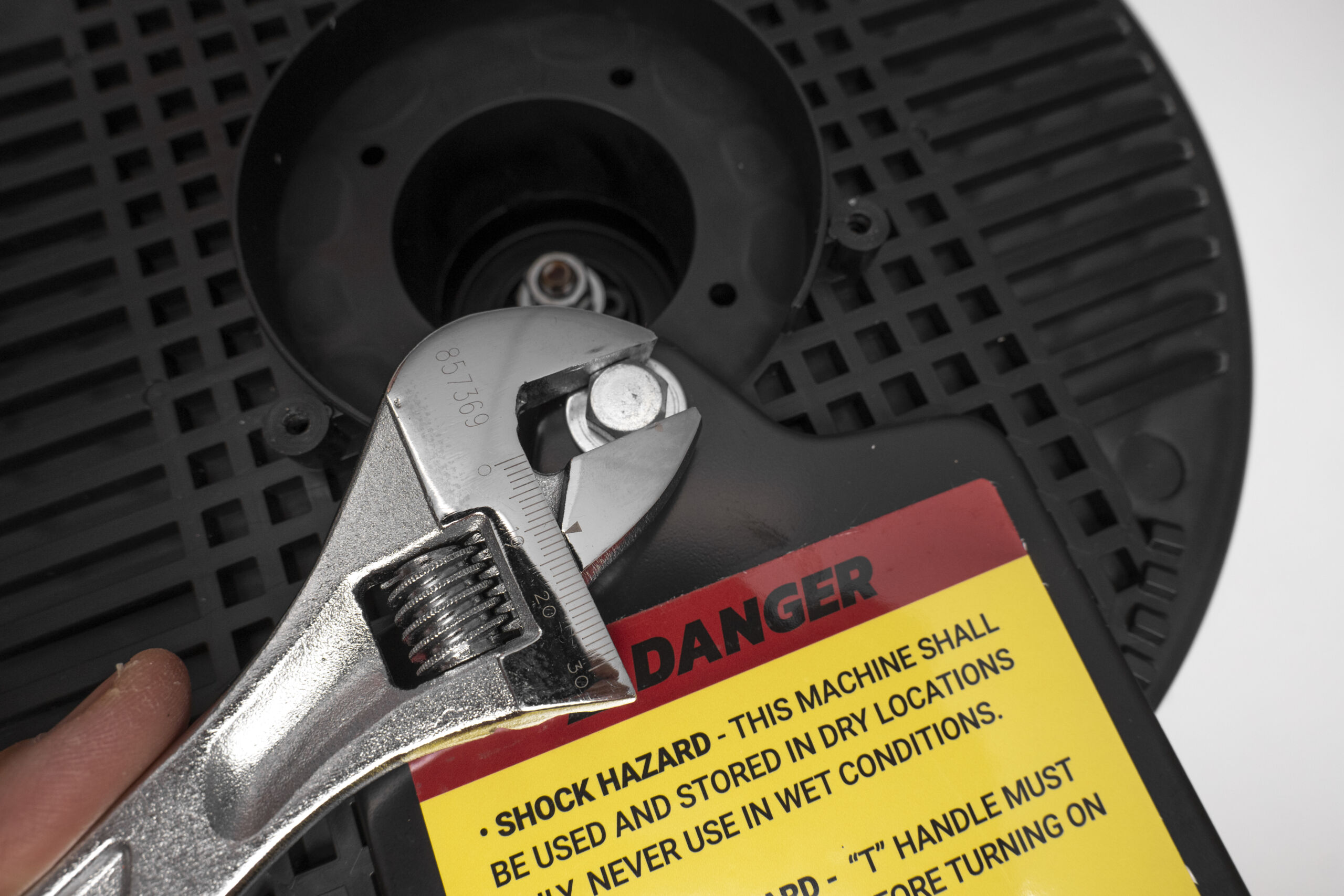
- Flip the machine over and with your adjustable wrench, reinstall the 12mm bolt and washer.

STEP 29 - SPINDLE COVER
- With your Phillips screwdriver, reattach the spindle cover with the 3 spindle cover screws.


STEP 30 - CONTROL BOX
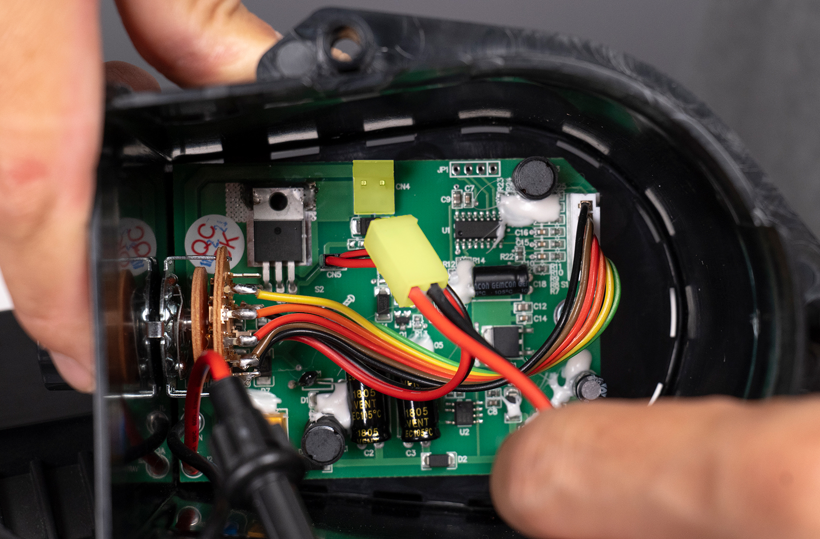
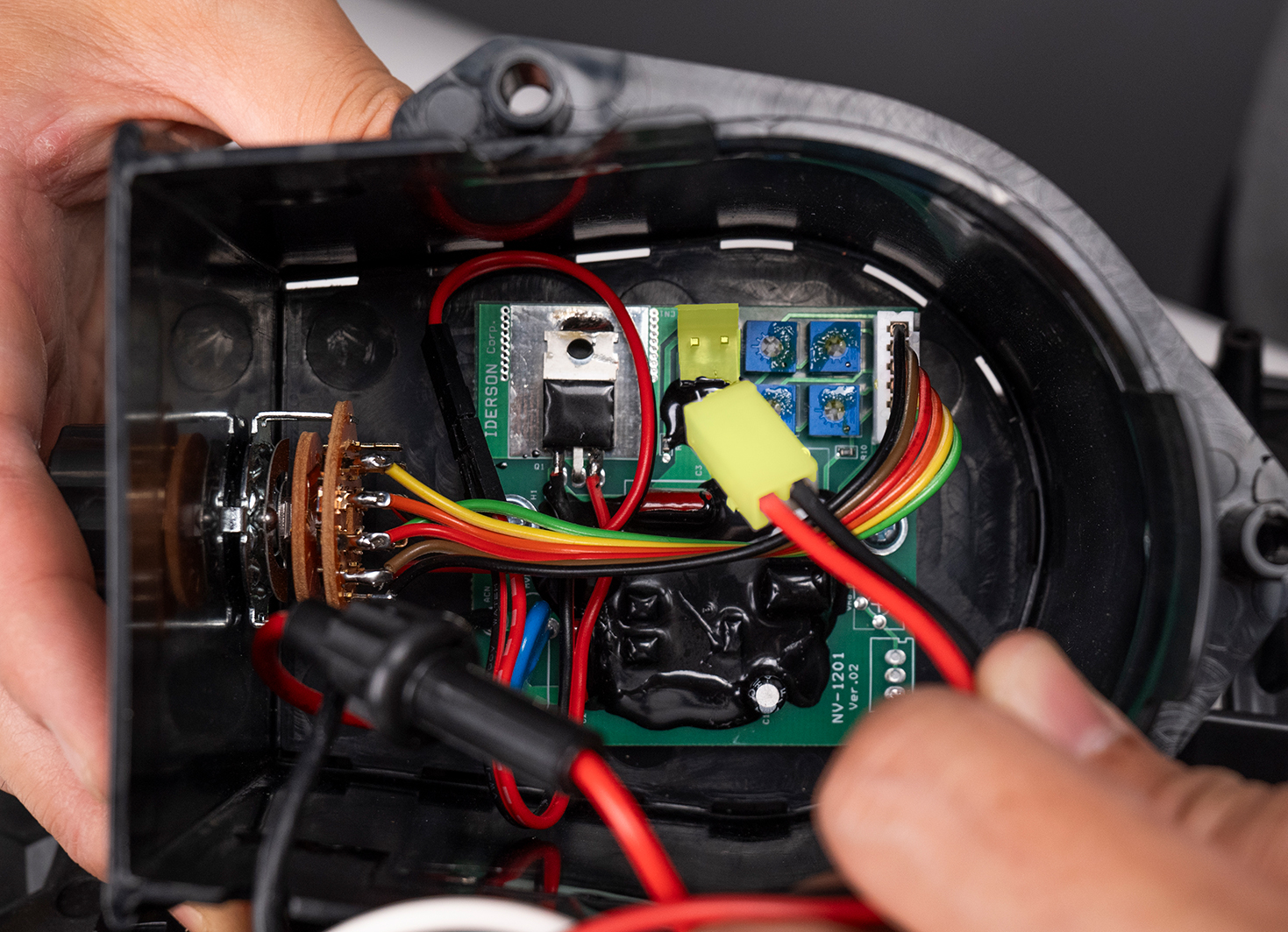
- Flip machine back over. Reconnect the power cable from the motor to the control board.
- NOTE: Image A is the new style board. Image B is the old style board.
STEP 31 - CONTROL BOX
- With your Phillips screwdriver, reconnect the ground wire (aqua color) with the ground wire screw from the board to the motor.

STEP 32 - CONTROL BOX
- Reconnect the control box back to the pitching machine and secure it with the 3 control box screws using your Phillips screwdriver.
- NOTE: Be sure all wires are carefully tucked back into the control box so none of them get pinched.
- NOTE: The plugged power cord gets slotted through the groove/indent on the control box.


STEP 33 - PINCH PAD
- Reinstall the pinch pad to the desired setting by sliding it into the top of the pitching machine.


STEP 34 - PINCH PAD
- Reinstall the 4 thumb screws that secure the pinch pad in the baseball or softball position setting.


