WARRANTY voided
These instructions are to guide those who want to self service their Launch F-lite™ Pitching Machine. The original warranty included with Launch F-lite™ Pitching Machine is void.
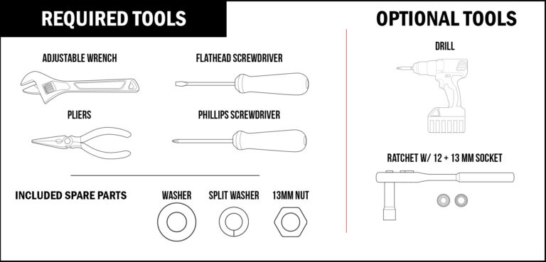
WHEEL REPLACEMENT Instructions
STEP 1 - UNPLUG MACHINE
WARNING
Please make sure the pitching machine is unplugged.
STEP 2 - THUMB SCREWS
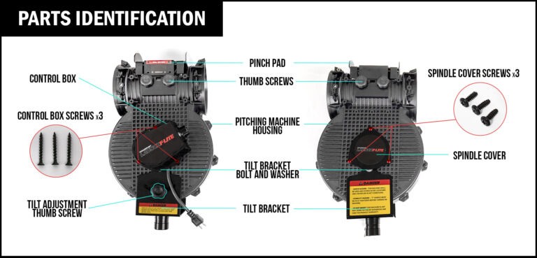
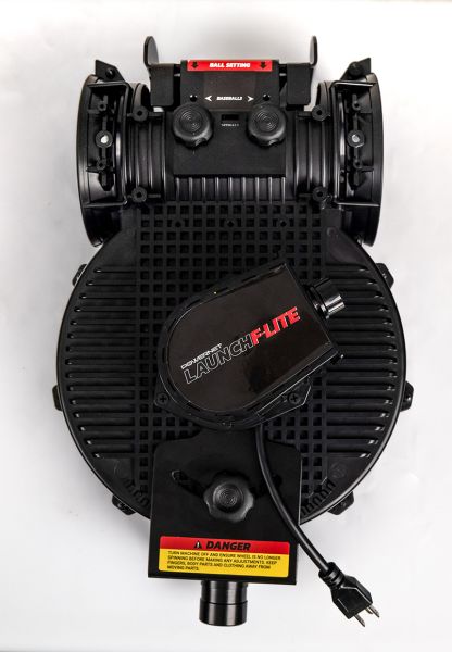
- Remove the thumb screws that secure the pinch pad.
- There are 4 thumb screws in total, 2 on each side.


STEP 3 - PINCH PAD
- Pull the pinch pad out.
- Once removed set it aside carefully.


STEP 4 - SPINDLE COVER
- With the pitching machine resting on the control box, remove the 3 spindle cover screws that secure the spindle cover with a Phillips screwdriver.
- Set the spindle cover and screws aside to be reused in a later step.


STEP 5 - TILT BRACKET
- You should now have access to the 12mm bolt and washer for the tilt bracket.
- With your adjustable wrench, remove the 12mm bolt and washer.


STEP 6 - CONTROL BOX
- Flip the machine over and using a Phillips screwdriver, remove the 3 control box screws.
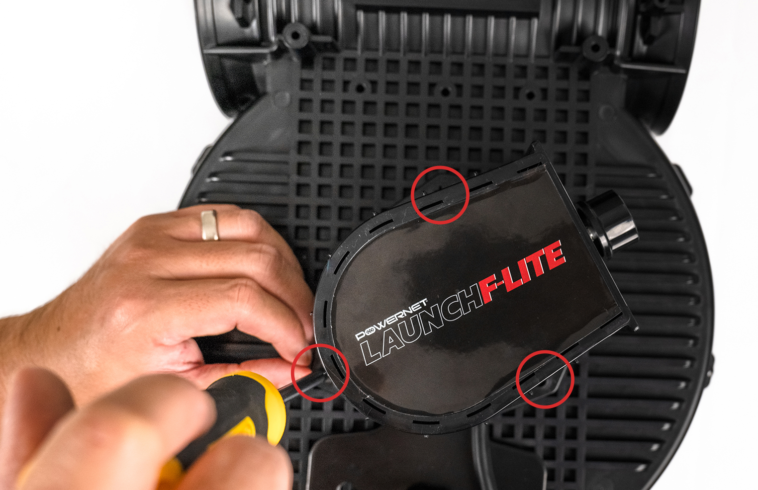

STEP 7 - CONTROL BOX
- Once the control box is free, very carefully lift it out of the way without pulling on any of the wires inside.

STEP 8 - CONTROL BOX
- Using a Phillips screwdriver, unscrew the ground wire screw to remove the ground wire (Aqua color) that is connected from the control board to the motor.
- Carefully set the ground wire screw aside to be used in a later step.

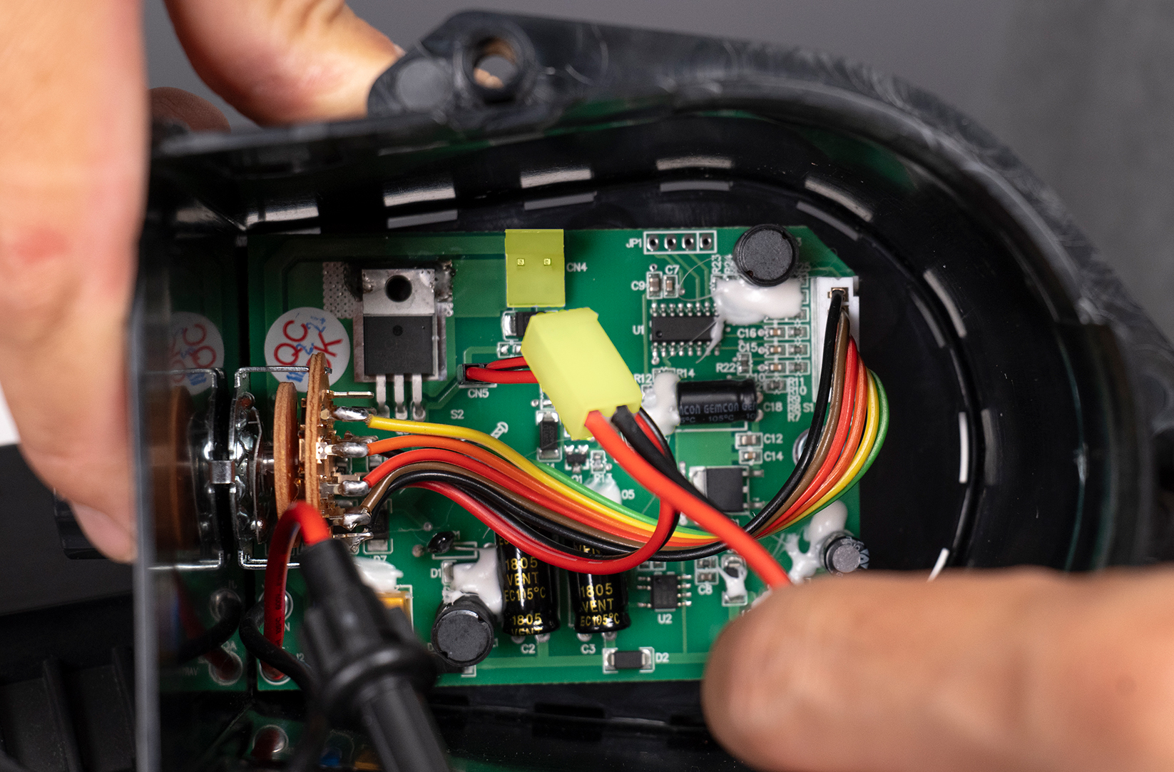
STEP 9 - POWER CABLE (NEW STYLE BOARD)
- Disconnect the 2-pin power cable (highlighted in yellow) by carefully lifting the locking tab to free the 2-pin power cable.
- Once the control box has been completely disconnected from the motor, set it aside for reassembly at a later step.
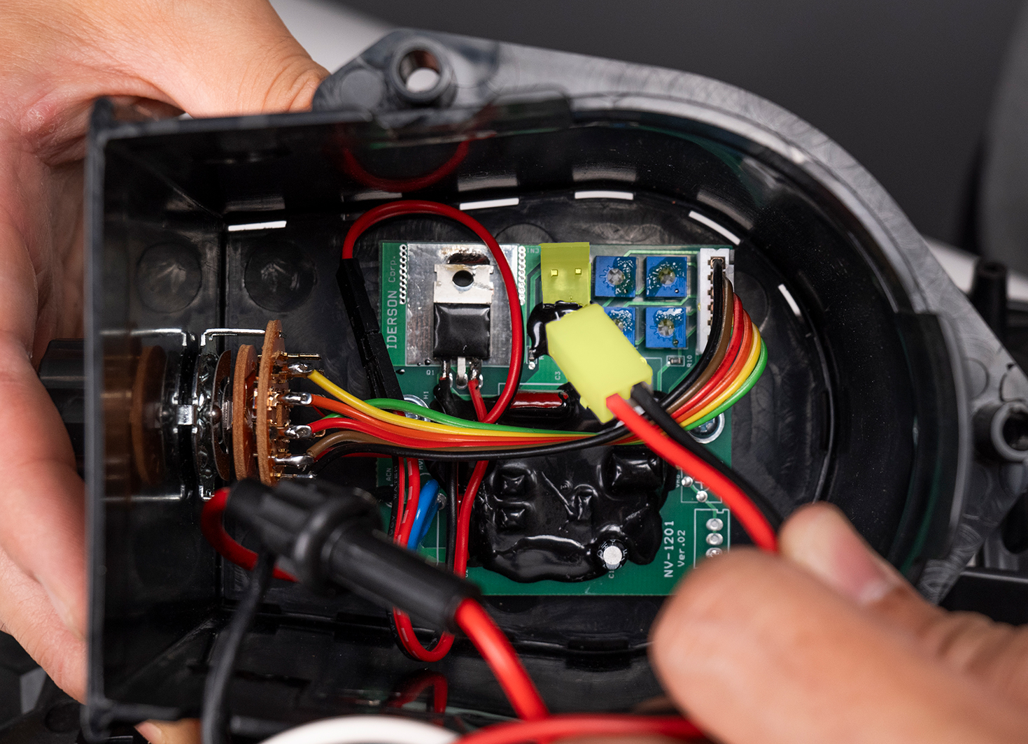
ALTERNATIVE STEP 9 - POWER CABLE (OLD STYLE BOARD)
- If you have the old style board, this step will look slightly different. Reference image.
- Disconnect the 2-pin power cable (highlighted in yellow) by carefully lifting the locking tab to free the 2-pin power cable.
- Once the control box has been completely disconnected from the motor, set it aside for reassembly at a later step.
STEP 10 - PITCHING MACHINE HOUSING
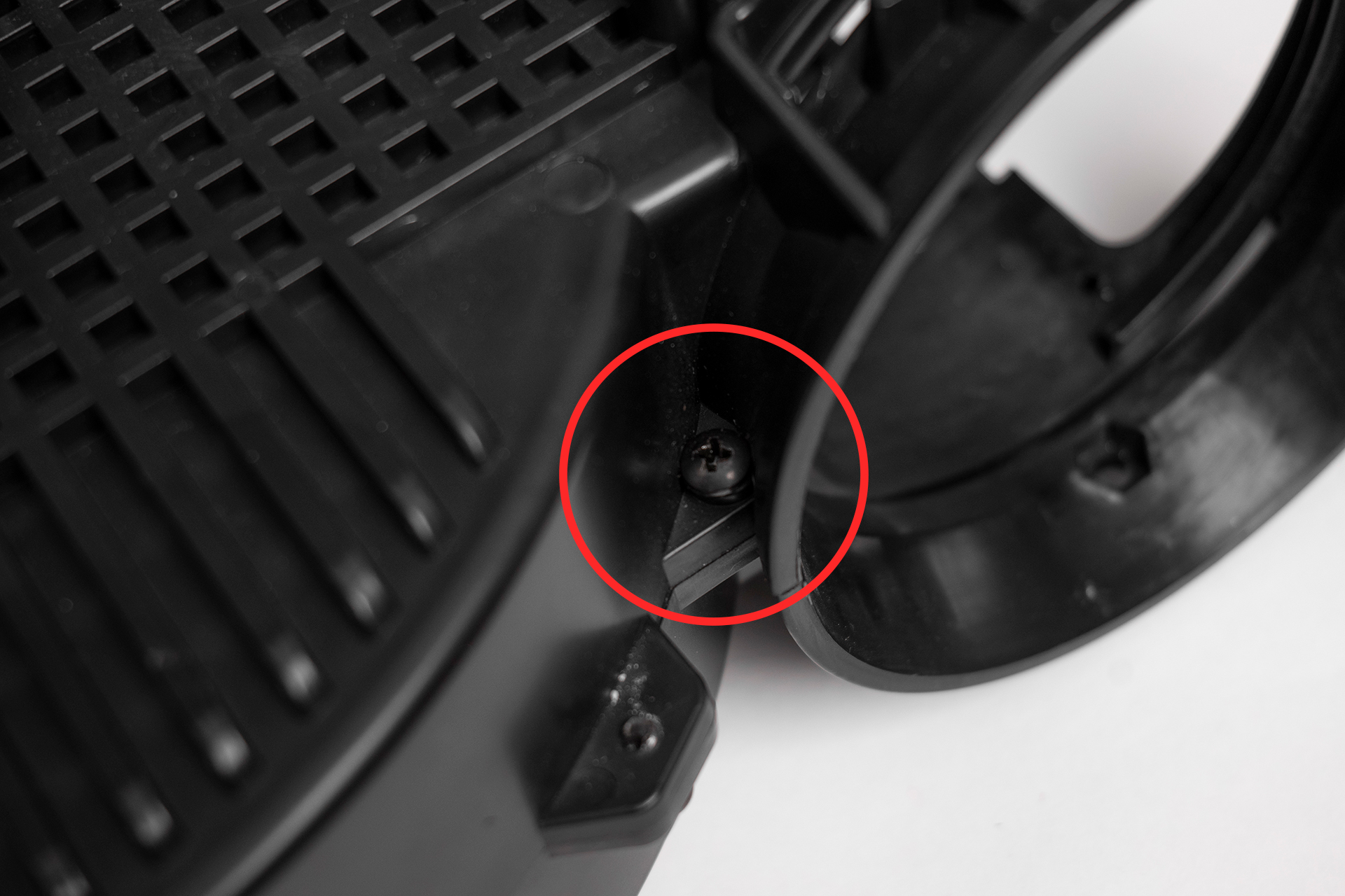
- Using a Phillips screwdriver, remove the front housing spacer by loosening the Philips head screw at the front of the pitching machine.
- NOTE: The Philips head screw is secured by a nut on the opposite side. You will need pliers to hold it from spinning while unscrewing the Philips head screw.

STEP 11 - TILT BRACKET
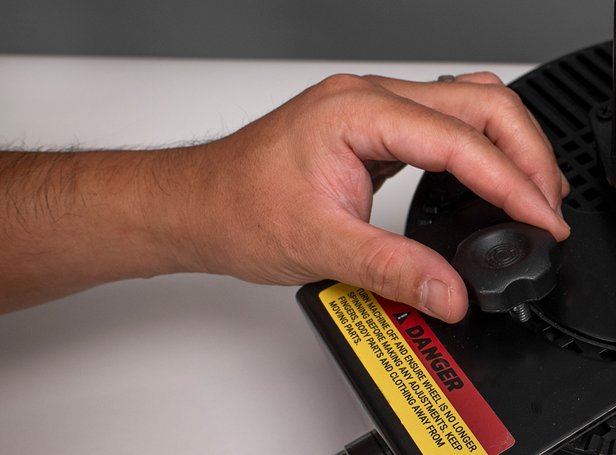
- Flip the pitching machine over so that the control box is facing up and remove the tilt adjustment thumb screw by unscrewing it.
STEP 12 - tilt bracket
- With your adjustable wrench, remove the remaining 12mm bolt and washer that secures the tilt bracket.

STEP 13 - TILT BRACKET
- Carefully slide the tilt bracket off and set it aside for reassembly at a later step.

STEP 14 - PITCHING MACHINE HOUSING
- With your Philips screwdriver, remove the Philips head screws that secure the two sides of the pitching machine housing.
- NOTE: There are 8 screws in total, 4 screws on each side with the screws alternating from front to back.


